ATtiny13 – Hello World! :)

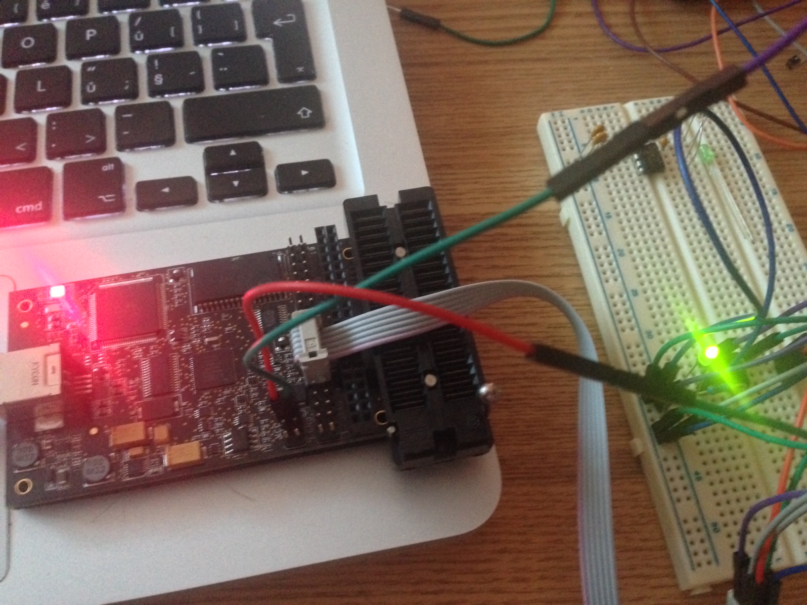
Finally managed to get into AVR programming. Using OSX, which I found as the worst platform for doing any kind of embed programming :( Sad. Anyway, there’s my first ATtiny schematics and code. I’m using AVR Dragon to flash code into the MCU.

tiny13-spi

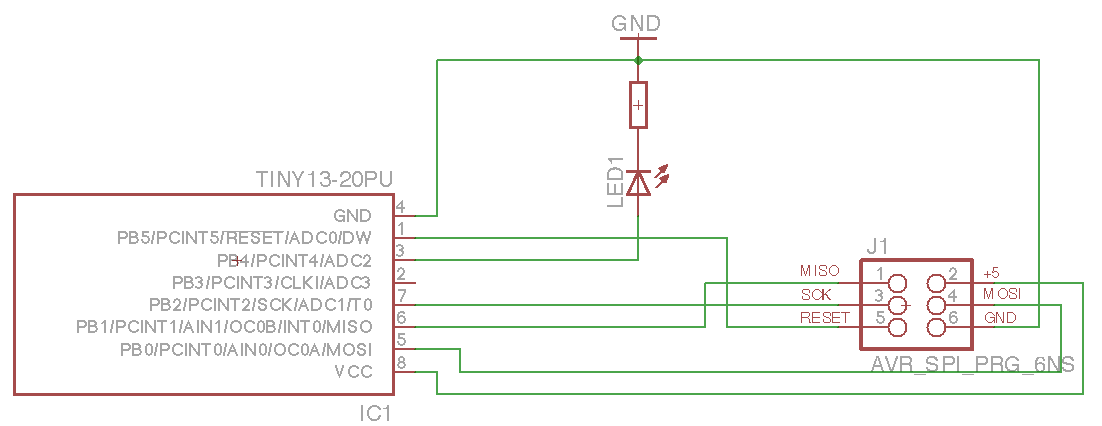
The circuit is quite simple. I just confirm SPI flashing works and I’m able to turn the LED on. So here’s some code (using avr-gcc to compile and avrdure to upload). Create new project using avr-project and add this to main.c file:

#include <avr/io.h>
#include <util/delay.h>

int main(void)
{
    const int msDelay = 50;

    // PortB pin4 to output (set bit to 1 using SHL)
    DDRB = 1<<DDB4;

    // PortB to low
    PORTB = 0;

    while (1) {
        // XOR on pin 4
        PORTB ^= 1<<PB4;
        _delay_ms(msDelay);
    }

    return 0;
}

Now we can compile the firmware and upload to our MCU.

$ make
avr-gcc -Wall -Os -DF_CPU=8000000 -mmcu=attiny13 -c main.c -o main.o
avr-gcc -Wall -Os -DF_CPU=8000000 -mmcu=attiny13 -o main.elf main.o
rm -f main.hex
avr-objcopy -j .text -j .data -O ihex main.elf main.hex
avr-size --format=avr --mcu=attiny13 main.elf
AVR Memory Usage
----------------
Device: attiny13

Program:      72 bytes (7.0% Full)
(.text + .data + .bootloader)

Data:          0 bytes (0.0% Full)
(.data + .bss + .noinit)

No errors. Great. Connect AVR Dragon and upload our new firmware:

$ make flash
avrdude -c dragon_isp -P usb -p attiny13 -U flash:w:main.hex:i

avrdude: AVR device initialized and ready to accept instructions

Reading | ################################################## | 100% 0.15s

avrdude: Device signature = 0x1e9007
avrdude: NOTE: "flash" memory has been specified, an erase cycle will be performed
         To disable this feature, specify the -D option.
avrdude: erasing chip
avrdude: reading input file "main.hex"
avrdude: writing flash (110 bytes):

Writing | ################################################## | 100% 0.46s

avrdude: 110 bytes of flash written
avrdude: verifying flash memory against main.hex:
avrdude: load data flash data from input file main.hex:
avrdude: input file main.hex contains 110 bytes
avrdude: reading on-chip flash data:

Reading | ################################################## | 100% 0.47s

avrdude: verifying ...
avrdude: 110 bytes of flash verified

avrdude: safemode: Fuses OK (H:FF, E:FF, L:6A)

avrdude done.  Thank you.

tiny13-spi-foto

For those, interested in .hex file – this is how it looks like:

$ cat main.hex
:1000000009C00EC00DC00CC00BC00AC009C008C09A
:1000100007C006C011241FBECFE9CDBF02D012C059
:10002000EFCF80E187BB18BA90E188B3892788BBFE
:100030002FE738E381E0215030408040E1F700C0F5
:080040000000F3CFF894FFCF9C
:00000001FF

and I made some commented assembler output (base is taken from avr-objdump -S main.elf).

 cat main.S

main.elf:     file format elf32-avr


Disassembly of section .text:

00000000 <__vectors>:
   0:	09 c0       	rjmp	.+18     	; 0x14 <__ctors_end>
   2:	0e c0       	rjmp	.+28     	; 0x20 <__bad_interrupt>
   4:	0d c0       	rjmp	.+26     	; 0x20 <__bad_interrupt>
   6:	0c c0       	rjmp	.+24     	; 0x20 <__bad_interrupt>
   8:	0b c0       	rjmp	.+22     	; 0x20 <__bad_interrupt>
   a:	0a c0       	rjmp	.+20     	; 0x20 <__bad_interrupt>
   c:	09 c0       	rjmp	.+18     	; 0x20 <__bad_interrupt>
   e:	08 c0       	rjmp	.+16     	; 0x20 <__bad_interrupt>
  10:	07 c0       	rjmp	.+14     	; 0x20 <__bad_interrupt>
  12:	06 c0       	rjmp	.+12     	; 0x20 <__bad_interrupt>

00000014 <__ctors_end>:             ; set stack to SRAM
  14:	11 24       	eor	r1, r1      ; set 0 to r1
  16:	1f be       	out	0x3f, r1	  ; 0 -> SPH
  18:	cf e9       	ldi	r28, 0x9F	  ; RAMEND
  1a:	cd bf       	out	0x3d, r28	  ; r28 -> SPL
  1c:	02 d0       	rcall	.+4      	; call main loop at 0x22
  1e:	12 c0       	rjmp	.+36     	; then call exit at 0x44

00000020 <__bad_interrupt>:
  20:	ef cf       	rjmp	.-34     	; 0x0 <__vectors>

00000022 <main>:
  22:	80 e1       	ldi	r24, 0x10	  ; 1<<DDB4 (0x10) -> r24
  24:	87 bb       	out	0x17, r24	  ; set r24 -> DDRB
  26:	18 ba       	out	0x18, r1	  ; set r1 (0) -> PORTB
  28:	90 e1       	ldi	r25, 0x10	  ; 1<<DDB4
  2a:	88 b3       	in	r24, 0x18	  ; read PORTB -> r24 to XOR
  2c:	89 27       	eor	r24, r25    ; XOR pin 4
  2e:	88 bb       	out	0x18, r24	  ; set r24 -> PORTB
  30:	2f e7       	ldi	r18, 0x7F	  ; 0x01387f = wait 79999 ticks (50ms at 4MHz)
  32:	38 e3       	ldi	r19, 0x38	  ;
  34:	81 e0       	ldi	r24, 0x01	  ;
  36:	21 50       	subi	r18, 0x01	; decrease r18 by 1
  38:	30 40       	sbci	r19, 0x00	; and decrease other by carry bit
  3a:	80 40       	sbci	r24, 0x00	;
  3c:	e1 f7       	brne	.-8      	; repeat until zero set - jump to 0x36
  3e:	00 c0       	rjmp	.+0      	; relative jump to 0x40
  40:	00 00       	nop             ; do nothing
  42:	f3 cf       	rjmp	.-26     	; jump back to 0x2a (loop)

00000044 <_exit>:
  44:	f8 94       	cli

00000046 <__stop_program>:
  46:	ff cf       	rjmp	.-2      	; 0x46 <__stop_program>


Blink LED2 – LPC1769

LPCXpresso finally beaten. Installed new v5, imported all the CMSIS needed and setup brand new, my very first, MCU example code :) I’m using LPC1769 sample board from Embedded Artists.

#ifdef __USE_CMSIS
#include "LPC17xx.h"
#endif

#include <cr_section_macros.h>
#include <NXP/crp.h>

// Variable to store CRP value in. Will be placed automatically
// by the linker when "Enable Code Read Protect" selected.
// See crp.h header for more information
__CRP const unsigned int CRP_WORD = CRP_NO_CRP ;

int main(void) {
    // Set P0_22 to 00 - GPIO
    LPC_PINCON->PINSEL1 &= (~(3 << 12));
    // Set GPIO - P0_22 - to be output
    LPC_GPIO0->FIODIR |= (1 << 22);

    volatile static uint32_t i;
    while (1) {
        LPC_GPIO0->FIOSET = (1 << 22); // Turn LED2 on
        for (i = 0; i < 1000000; i++);
        LPC_GPIO0->FIOCLR = (1 << 22); // Turn LED2 off
        for (i = 0; i < 1000000; i++);
    }
    return 0;
}

and the same in assembler (from http://pygmy.utoh.org/riscy/cortex/led-lpc17xx.html)

;;; led-lpc17xx.asm
;;; written by Frank Sergeant
;;;    frank@pygmy.utoh.org
;;;    http://pygmy.utoh.org/riscy
;;; This program is in the public domain.  See http://pygmy.utoh.org/riscy/cortex/
;;; for notes about the program and how to assemble, link, and burn to flash.

;;; Blink the LED on the LPCXpresso LPC1769 ARM Cortex M3 board
;;; (or any LPC17xx ARM board with perhaps minor modifications).

;;; The LED on the Xpresso board is labeled LED2 and is just to the
;;; left of (inside of) J6-36.  It is connected to P0.22. The LED is
;;; on when P0.22 is high.
        
;;; Directives
        .thumb                  ; (same as saying '.code 16')
        .syntax unified

;;; Equates

        .equ LED_MASK, 0x00400000 ; i.e., bit 22
        
        .equ PINSEL0,  0x4002C000
        .equ PINSEL1,  0x4002C004

        .equ FIO0DIR,      0x2009C000 ; port direction, 0 (default) = input
        .equ FIO0MASK,     0x2009C010 ; port direction, 0 (default) = input
        .equ FIO0PIN,      0x2009C014
        .equ FIO0SET,      0x2009C018
        .equ FIO0CLR,      0x2009C01C
        
        .equ STACKINIT,   0x10004000

        .equ LEDDELAY,    300000

.section .text
        .org 0

;;; Vectors
vectors:
        .word STACKINIT         ; stack pointer value when stack is empty
        .word _start + 1        ; reset vector (manually adjust to odd for thumb)
        .word _nmi_handler + 1  ;
        .word _hard_fault  + 1  ;
        .word _memory_fault + 1 ;
        .word _bus_fault + 1    ;
        .word _usage_fault + 1  ;

_start:

        ldr r6, = PINSEL1
        ;; set P0.22 as a GPIO pin
        ;; P0.22 is controlled by bits 13:12 of PINSEL1
        ;; xxxx xxxx xxxx xxxx xx11 xxxx xxxx xxxx
        ;;    0    0    0    0    3    0    0    0

        ldr r0, [r6]
        bic r0, r0, # 0x00003000  ; clear bits 13:12 to force GPIO mode
        str r0, [r6]


        ;; set LED output pin (i.e. P0.22) as an output
        ldr r6, = FIO0DIR             ; for PORT0
        mov r0, # LED_MASK            ;  all inputs except for pin 22
        str r0, [r6]
        
        ;; r0 still contains LED_MASK 
        ldr r5, = FIO0CLR
        ldr r6, = FIO0SET

loop:
        str r0, [r5]            ; clear P0.22, turning off LED
        ldr r1, = LEDDELAY
delay1:
        subs r1, 1
        bne delay1

        str r0, [r6]            ; set P0.22, turning on LED
        ldr r1, = LEDDELAY
delay2:
        subs r1, 1
        bne delay2

        b loop                 ; continue forever

_dummy:                        ; if any int gets triggered, just hang in a loop
_nmi_handler:
_hard_fault:
_memory_fault:
_bus_fault:
_usage_fault:
        add r0, 1
        add r1, 1
        b _dummy