As I’m building my own IQ house control system, I need to have RTC in my system. So started playing with MCP7940N and i2c interface. I’m using Raspberry Pi for my experiments with i2c/SPI.
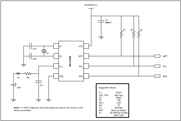
Construction is pretty simple, just use MCP7840N Datasheet.
Then you can start checking with Pi. In my case, I’m using RevB, so my bus has number 1 and RTC got 0x6f address.
root@pi:~# i2cdetect -y 1
     0  1  2  3  4  5  6  7  8  9  a  b  c  d  e  f
00:          -- -- -- -- -- -- -- -- -- -- -- -- --
10: -- -- -- -- -- -- -- -- -- -- -- -- -- -- -- --
20: -- -- -- -- -- -- -- -- -- -- -- -- -- -- -- --
30: -- -- -- -- -- -- -- -- -- -- -- UU -- -- -- --
40: -- -- -- -- -- -- -- -- -- -- -- -- -- -- -- --
50: -- -- -- -- -- -- -- -- -- -- -- -- -- -- -- --
60: -- -- -- -- -- -- -- -- -- -- -- -- -- -- -- 6f
70: -- -- -- -- -- -- -- --
what next? Check address 0x00, if the onboard oscilator is running
root@pi:~# i2cget -y 1 0x6f 0x00 b
0x00
0x00 means NO, it’s NOT running. So, turn it on
root@pi:~# i2cset -y1 1 0x6f 0x00 0x80
and check few times address 0x00
root@pi:~# i2cget -y 1 0x6f 0x00 b
0x87
root@pi:~# i2cget -y 1 0x6f 0x00 b
0x88
root@pi:~# i2cget -y 1 0x6f 0x00 b
0x89
root@pi:~# i2cget -y 1 0x6f 0x00 b
0x90
root@pi:~# i2cget -y 1 0x6f 0x00 b
0x91
Increments! Great. That means – our oscilator is working = our clock is working too. Next step is to set current time and date. But wait. How are values stored and read/written? RTC uses BCD encoding for values, that means, eg. number 94 is stored as 9 and 4, both in 4 bits = 9 is stored as 1001 and 4 as 0100, in hexadecimal 0x94. Easy? Eg. day is using 6 bits, upper two for 0123 values, bottom bits for 0-9, so 31th will be stored as 0x31. For more details please read the PDF – RTCC Memory map. So back to setting the date & time:
# 2nd Feb 2014
root@pi:~# i2cset -y 1 0x6f 0x06 0x14
root@pi:~# i2cset -y 1 0x6f 0x05 0x02
root@pi:~# i2cset -y 1 0x6f 0x04 0x19
# 00:02:00
root@pi:~# i2cset -y 1 0x6f 0x02 0x00
root@pi:~# i2cset -y 1 0x6f 0x01 0x02
root@pi:~# i2cset -y 1 0x6f 0x01 0x80
Fine. But if we’re setting ’00’ as seconds – address 0x00 – why value 0x80? 7th bit = ST – onboard oscilator enabled.
I’ve written simple Python code to read from RTC and print out the value:
from time import sleep
import smbus
import time
import signal
import sys

bus = smbus.SMBus(1)
RTC_ADDR = 0x6f

ADDR_SEC = 0x00
ADDR_MIN = 0x01
ADDR_HOUR = 0x02

def signal_handler(signal, frame):
  sys.exit(0)

def bcd2bin(x):
  return (((x) & 0x0f) + ((x) >> 4) * 10)

if __name__ == "__main__":
  signal.signal(signal.SIGINT, signal_handler)
  while True:
    sec = bcd2bin(bus.read_byte_data(RTC_ADDR, ADDR_SEC) & 0x7f)
    min = bcd2bin(bus.read_byte_data(RTC_ADDR, ADDR_MIN) & 0x7f)
    hour = bcd2bin(bus.read_byte_data(RTC_ADDR, ADDR_HOUR) & 0x3f)
    print "%02d:%02d:%02d" % (hour, min, sec)
    sleep(0.9) # nearly 1 sec
Just run by
root@pi:~# python rtc.py
00:35:41
00:35:42
00:35:43
00:35:44
00:35:45
00:35:46
Voila! :) RTC is up and running. I’d like to check tomorrow (resp. today) morning, if everything is still working correctly, and can create next module for my IQ house control system :)